Previous
Tool / Carving Tips
Updated 05/31/2018
All tool tips are subject to copyright laws, and may only be used with authorization
from PJL Enterprises or the original author.
1997:
May Tool Tip: Its
about burner cords, and how to keep them from being a "drag".
June Tool Tip: Some tips on transferring your design to wood.
July Tool Tip: This months tip is on
collet and bit care.
September Tool Tip: Some alternative ways
to clean your burning tips.
November Tool Tip: A
"Sticky" Situation, and how to avoid it.
December Tool Tip: A few
computer pointers.
1998
March Tool Tip: How
to use the number "13" pen tip to make fish scales.
April Tool Tip: A Beeswax finish, used on
fine violins.
May-June Tool Tip: Another
use for your pyrographic burner unit.
July-August Tool Tip: How to make
pictures of your carvings download fast (for carver websites).
Nov~Dec Tool Tip: A
discussion about dust collectors. Design do's and don'ts.
1999
July-August Tool Tip: Pyrography systems,
theory and application.
2000
January Tool Tip: An
easy way to make a lateral line on fish carvings.
October Tool
Tip: Another way to transfer patterns to wood.
December Tool Tip: How to make fuzzy hair, for
my teddy bear.
2012
January Tool Tip: Total Cost of Ownership (TCO)
or How much does that tool "really" cost?
2015
October Tool Tip: Going, Going, Gone... or How
to prevent your pyrographic art from fading
This month's tip is about burner cords,
and how to keep them from being a "drag".
Because our pens are so light weight to begin with, even our superflex
cord can seem like a "dog's tail" that your having to "drag" around
with the pen whilst burning. To remedy this problem, I suggest that you first find a
fairly small rubber band. Next, on the end of the cord that attaches to the pen, fold the
cord over onto itself once. Use the rubber band to secure the cord, so it stays folded
over onto itself.
Now when using your pen, just have the cord go between your thumb and
trigger finger so it rests in your palm. You'll be amazed how your cord creates no
"drag" now. Some people even use an armband to have the cord follow their
forearm, so that the cord is totally out of the way.
Originally told to me by Laurie Gmyrek and Steven
Chlupsa.
Back to top
This month's tip is about relief carving, and an easy way
to do lettering. Also some tips on going about transferring it to your wood.
For anybody who has the need to do some lettering, to
eliminate the chore of setting it out. May I suggest a visit to this site and pick up a
shareware copy of an easy to use program called poster, that takes all the hard work out
of it. Poster Software
(http://users.aol.com/PosterSW/)
This little jewel was submitted to Bill Judt's woodcarving
list (http://wwwoodcarver.com/WWWList/WWWList.html) by a Malcolm Chorley I believe, and talked about by many others.
Another subject that kind of goes along with this, is
transferring a pattern to a block of wood. This too has been discussed at length on the
previously mentioned list server. Various techniques can be used, from using plain carbon
paper and tracing your design, to laser printing or photo copying a "reversed"
image and ironing it onto your wood.
If you own an ink-jet printer, you can do the same thing as
you would with a laser printer, except that you print it on acetate transparency film and
immediately press it to the block of wood using a roller or squeegee, (ink-jet ink doesn't
dry very fast on regular transparency film). The acetate can be cleaned with a damp cloth,
towel dried, and reused many times. This is something I developed for my mom's arts &
craft business, works great for intricate patterns and curved surfaces. When doing a
"production run", I can usually get each print impression to transfer twice;
although the second one may be a bit light. Of course, this doesn't work to hot (no
pun intended) with flat work pyrography, as there is no way to erase pattern lines (i.e.
it works best for tole painting or sculpture pattern cutting).
As with anything you haven't tried before, use a scrap
piece of wood to test with first, it also helps if the surface of the wood is fairly
smooth.
Back to top
This months tip is on collet and bit care, submitted by Laurie Lundell (Gmyrek)
Ever bent your favorite bit trying to get it out of the collet, or just
hate the hassle of trying to get a stuck bit out of a collet? You might be thinking,
"just unlock the collet, and push the bit in further if possible". That will
work, but you might damage your bit if your not careful. The real cause is that the
insides of your collet(s) have wood resin build up, which causes the collet to kind of
glue itself to the bit.
To clean (for example an Optima 2 hand piece) your collet set, you can
use a few items usually found around the house. Soaking the collets (and collet cap) in
plain finger nail polish remover or rubbing alcohol (oven cleaner will work too, but keep
it off of any aluminum parts) will quickly remove any resins. The parts of the hand piece
shaft that the collet(s) have contact with should be cleaned with the same thing, using a damp
(not dripping wet) cotton swab. DO NOT get any of the cleaning solution
on any bearing, as it may penetrate and damage it which will lead to premature bearing
failure. Finish by drying the collets and other parts (use a thin wire to thread a thin
piece of yarn through the collet holes for drying, do not force it through), and then
giving them a thin coat of light oil (like WD-40), and wipe clean again with a cloth or
Q-tip. Again, DO NOT get any of the light oil on the bearings.
If you have very humid conditions like Minnesota does, another cause of
stuck bits is plain old rust. On bits that have already succumb to the ravages of moisture
and are rusted...Spray with WD-40 or oven cleaner in a cup and let them soak...then take a
wire brush to them and/or steel wool to the shank, wipe clean, spray again, then wipe
clean...voila......like new! it is a good idea to spray all of your bits with a little
WD-40 from time to time to prevent rust in the first place.
Back to top
I have never been one burn light when using my burning
pens. I am also too lazy or too busy to constantly buff off carbon build up when using
them (I usually use them to "score" plastic). This of course leads to heavy
carbon build up on my tips, to the point that it can't be easily buffed off. I am also
aware that heavily buffing a tip can cause the metal on the side of the tip to "roll
over" the sharpened edge. Which would mean I'd have to then resharpen my pen tip to
burn a decent line, which of course will lead to a shorter tip life, etc, etc....
If you too have these bad habits, don't reach for the
sandpaper just yet... Their is an amazingly simple and inexpensive solution to this
problem. You probably already have this product somewhere in your house. Go look on your
shelves, or under the sink for that can of oven cleaner. Yes, oven cleaner!
Be mindful to read your oven cleaner directions, as it may
be harmful to certain metals (not to mention yourself). The nichrome tip itself should not
be a problem, but the the brass tubes and silver solder that is connected to the nichrome
tip may not like certain oven cleaners. If so, just be careful not to let the oven
cleaning foam or gel touch the silver solder or brass parts of the pen.
I myself like to use "Diablo Carbon Kleen", which
is safe for all metals (but still pretty toxic). This stuff is a gel like substance that
comes in a can. You'll have to go to a restaurant supply store to find it though. An
overnight soak, then wiped clean, followed by another two hour soak usually gets 90% of
the carbon off of my once heavily carboned tips. At that point I can usually buff off the
remaining carbon build up with ease.
You may have to experiment with your particular oven
cleaner to see what the optimum soak time(s) will be, and whether you'll need to do it
more than once or twice.
Back to top
This month's tip was submitted by Laurie Gmyrek. Laurie is an
accomplished wood carving artist who also does stained glass. Visit her web site to see some of
her past and present works.
A "Sticky" Situation
In competition, we are subject to stickers being placed on our carvings,
for identification purposes. This year I have a piece that has been damaged by a sticker,
twice. The damage did not occur until the sticker was removed. When this was done, the
finish, the paint and the gesso under-coating, came off with the sticker, leaving only the
deft-sealed wood behind.
The repair of this seems simple enough, but just painting the damage does not fill in the
thickness of the surface that was removed. Try as I may, the color was right, but from the
side, in the right light, the slight depression can be seen. The only way to rectify this
would be to start from scratch by removing the surface treatment completely and starting
over with a new finish. Unfortunately this is not always possible, and a real pain in the
neck!
Until the competitions use stickers, which are "surface friendly", this kind of
damage along with adhesive being left behind, can occur. My tip for this month would be to
use a hairdryer to heat the sticker and it’s adhesive, prior to trying to remove the
sticker. This seems to solve the problem, but you need to remember to do this, prior to
attempting to remove the sticker.
Hopefully this tip can keep someone else from having to deal with a "sticky"
situation.
Laurie J. Lundell Gmyrek
Back to top
This month I thought I'd would give a computer few pointers. Yes, I know
it really has nothing to do with carving or carving tools "directly", but you
are using your computer to view this (aren't you?).
Arghhh! My internet connection is too
slow!
A few months back I purchased a brand new 33.6 Cardinal modem. To my
disgust, it didn't seem that much faster than my old modem (a zoomview 14.4bps). After
much internet searching, I came across a web sight called Windows 95 Annoyances
which was very informative on what the "real" problem was (it has many other
windows95 fixes too). Windows 95, by default, is optimized to run on a LAN or Ethernet
like connection, which have considerably higher bandwidth compared to a 33.6 modem. There
is a setting in the Registry file called "MAXMTU", which is set to 1500 by
default. This high of setting can cause a router (between you and the site your looking
at) to "hang", or send IP packets out of sequence. At any rate I edited my
registry file, and gained at least a 100% speed up when downloading a web site or file. Of
course most people are not technically inclined enough to even think about rooting around
the registry file, so an easier (and just as effective) way to fix this is to get a FREE
program called "Mtuspeed" at the MTU-Speed Home Page.
Like anything else, remember to read the program directions first.
Drat! My friend is online again, so I
can't call him/her!
To see if a friend or relative is currently online, get a program called
ICQ (Sounds like: I seek you) from Mirabilis. Of course the person your looking for must also have this
program, have it running whilst online, and be in "online" mode to be seen. ICQ
not only lets you know if a given person is online, but will also let you start up a chat
window with them (more than 2 can be in a chat session). You can even use it to run 3rd
party communications programs like Microsoft NetMeeting, send URLs, send or receive files,
send and receive quick messages, and much much more.
Help for the carvers web site (with large
photos).
You'd like to set up a web site to show off your carvings and you have all
the equipment you need, but you don't have a clue when it comes to html coding. Neither
did I for the most part. For about $150.00 (or less) you can get Frontpage98, which is
pretty much like working with a work processor (no knowledge of html is necessary). This
entire web site was made using Frontpage97, and required very little manual coding of html
code. I hear that FP98 is even better than FP97.
When designing your web site, you can get some ideas by looking at how
other people have done theirs (go to my links page for some good
examples). Some design caveats that should be followed: 1. DO NOT to have pages buried
more than five layers deep from the initial start page of your site (makes it hard for
people to navigate your site). 2. If using frame sets, remember to also have your site
links (and email link) somewhere on each page (in case the person's browser doesn't
support frame sets). 3. PLEASE pick a text color and background color or bitmap image that
does not cause blindness (yellow text on a cyan background comes to mind ;-) 4.
Have a few people you know (with different screen resolutions and different browser
software) test out the "viewability" of your site, as it may look totally
different from what you see on your screen...
Looking at web sites with photos of carvings is getting to be a hobby with
me ;-) The one thing that can really distract a person viewing a site are BIG JPEG files
that seem to take forever to download. A neat little program, called Cyberview, can help cut the fat out
of your large JPEG files. Remember to always save your JPEG files at 100% quality before
using Cyberview, in the same "size" (height & width) as you want them to
display on the browser, and that 96 dpi (dots per inch) is sufficient for most people.
(640x480 screen resolution is equal to 72 dpi, 800x600 = 96dpi.)
Another thing to consider is how you scanned a photo of a carving to begin
with. A wealth of general information about scanning techniques can be found at Wayne's Scanner Page.
Another tip (I don't remember if Wayne mentions it) is to never
save your newly scanned file as a JPEG file. Why?!? The JPEG file format should only be
used after ALL of your editing is completely done. I use the compressed TIFF
format, then save the final edited version as a JPEG. For example: If you open a
previously saved JPEG file, and then run an "unsharp-mask" (sharpening) function
on it, it may get blocky and somewhat pixilated (sharpening a JPEG file has a tendency to
make "defects" in the compression process show up). In fact; if you open, edit,
and save to a JPEG file several times, the image quality will noticeably degrade.
GIF vs. JPEG: Using the wrong file format can cause a given image to be
too large and/or look bad. A general rule of thumb to follow is: JPEG format should be
used for 24bit photographic files only. It is not very good at compressing
computer generated vector graphics (like text or icons). The GIF format is best suited for
computer generated graphics and text. You can use GIF for small "thumbnail"
photos, but they will have to be in an eight bit format (256 colors), and photos are
smallest with a "diffusion screen dither".
Whew! I hope these tips will help out you wanna-be webmasters in getting
that perfect carving site, up and running.
Back to top
This month I'll be showing the technique of how to use the number
"13" pen tip to make fish scales. This technique was originally shown to me by
Scott Clinton at last years Northern Nationals in Bloomington, MN. I believe that Scott is
the originator of this technique, and teaches it to his students.
Step 1, the scale.
 As shown here to the left, you make each individual scale by holding the pen's
flat surface to the wood and making a crescent however wide you need it to be. Keep the
pen tip orientated the same throughout the stroke. Use the pen's heat and shape to depress
the wood more in the middle third of the stroke, and depress a bit lighter on the ends.
You'll find that rotating the the tip slightly as your doing a scale, makes it a bit
easier to control.
As shown here to the left, you make each individual scale by holding the pen's
flat surface to the wood and making a crescent however wide you need it to be. Keep the
pen tip orientated the same throughout the stroke. Use the pen's heat and shape to depress
the wood more in the middle third of the stroke, and depress a bit lighter on the ends.
You'll find that rotating the the tip slightly as your doing a scale, makes it a bit
easier to control.
Step 2, the second scale..
 Make another like the first one, starting at about a bit more than a third to
a half of a scale width over from the first one.
Make another like the first one, starting at about a bit more than a third to
a half of a scale width over from the first one.
Step 3, the third and final scale...
 The "joining scale" is made pretty much like your first two, and
should connect approximately* 1/3 from the end of each of the two scales it is connected
to. Voila, you've just learned the three basic steps to fish-scale carving using our
number 13 pen tip.
The "joining scale" is made pretty much like your first two, and
should connect approximately* 1/3 from the end of each of the two scales it is connected
to. Voila, you've just learned the three basic steps to fish-scale carving using our
number 13 pen tip.
Some Additional Notes.
Obviously not every scale on a fish is going to be the same size, as you
will need to have smaller ones near the belly, gills, and tail fins among other places.
The beauty of this technique is that you can rapidly change scale sizes, and can be done
in reverse of what I've shown here (start with bottom scale, then make the other two on
top, etc...). Another advantage of this tip and technique is quite evident when doing the
inside of a curved fish body (hard, if not impossible, to do with most other types of
scaling tips). Remember, this "basic" technique is not set in stone, and can be
strayed from somewhat liberally to get the effect that you need (i.e. every scale should
not meet "exactly" 1/3 from the edge of the adjoining scales, as in real life...
everything is approximate....).
If your having a hard time going from one side of the scale to the other
evenly, you can alternatively go from each end of a scale and join it in the center. This
is usually the easiest for beginners, or if you have limited dexterity. This technique is
easiest if you don't try to "over texture" your fish. Most fresh water fish I've
handled do not have a very deep texture to their scales any ways.
Many carvers draw out with a pencil where they intend to burn their
carvings, this is not necessary or even recommended. Because this is somewhat of a
"freeform" way of making fish scales, it is very hard to try and stick to a
drawn pattern whilst doing. If you make a mistake while burning, oh well... Fish don't
have perfect scales any ways, and you can easily cover up an occasional mistake by making
it look like a scar or "mutant" scale. To illustrate, my daughter caught a sun
fish last summer that had a good sized chunk of meat removed towards the front of its
dorsal fin, which had even regrown scales over the scar.
This pen tip is available in three sizes: Small, Medium, and Large. The
small one is good for doing miniatures, trout scales, or if you prefer it to the medium
size for doing the smaller scales on your carving. The Medium sized tip is the most
versatile, and can be used to do all of the scales on most life sized fish carvings. The
Large sized tip is good for when your working on big carvings or scales, and can do most
of the same work the Medium is capable of (really small scales are nearly impossible
though). The size of tip you choose primarily depends on the size of your work, and your
personal preferences.
This pen is offered in both standard and heavy duty styles, but I
recommend getting it in the heavy duty style along with a heavy duty cord too. This pen
began life for use in flat work pyrography, and is slightly different from the original in
that the tip should not come to a "sharp" point. Instead, its tip is "very
slightly" rounded at the point, so that it doesn't gouge when you are in the middle
of the scale stroke. If you get this tip, or have a similar one, you can remove any sharp
point by just running the point across a piece of sand paper once (once is usually
enough).
Back to top
This month's tip was contributed by Michael Dunn, a multi-talented
artist who has a very interesting and unique website of his own. This is how the
"professionals" in Switzerland finish violins, so now you know another little
secret ;-).
When I was in Brienz, Switzerland learning to carve at the
Schnitzlerschule there, they had a section of their school devoted to violin making. The
basic final finish was beautiful, and I found out its also very simple.
Shave beeswax into a small jar, press down firmly but not hard enough to
make it a wad again, and then cover it with turpentine and let it sit overnight in a warm
place. In the morning you'll have a paste or thick liquid, depending on the ratio of wax
to turpentine. You can adjust it by adding one or the other. I prefer a thick paste.
anyway, you rub it on like any wax, and wipe it off lightly to get any thick places
smoothed out. Let it sit for 24 hours, and rub it out again, hard until its shiny. Do it
again twice, same time interval, and then polish it smooth.
It may take some work, but its the best final finish I ever ran across.
Ideally you would re-wax it about once a month for a few months, and then once a year to
bring out the shine again. It gets better each time, and it'll take the three initial
coats to look right.
Back to top
This month's tip was originally shown to me by Steve
Chlupsa, president of SMC Enterprises.
If you have a pyrographic burner, like the Optima 1 for example, it can be
used for texturing / burnishing / cutting wood, leather, gourds, AND airbrushing. Yes,
airbrushing! Well, making stencils for airbrushing at any rate ;-)
Many carvers and airbrush artists use an acetate or frisk mask to better
control where the paint is applied to. If you have a pyrographic burner unit that has
stable lower temperature settings (like the Optima 1 does), it can be used to
"score" acetate and similar masking materials instead of using an exacto knife
or razor blade. In fact it works much better than exacto knives and razors, as you have a
sharp "heated" blade. Its also much safer, as your less likely to cut yourself
using this technique than you would with a razor or an exacto knife.
With this technique, you can use thicker acetate that what you would
normally use for airbrush masking (it won't tear as easily). If you want to print a
pattern onto it first using a computer printer or copier onto standard or inkjet
transparency, that will work just fine too. After you've drawn, printed or copied your
pattern to the acetate, you'll want a score it on a glass surface (won't dull the blade,
hard backstop). BTW, A back-lit glass top table works excellent for doing this. You'll
want to make sure your burning pen tips are sharpened AND polished, as it works much
better if they are polished (glides better, acts sharper, no "burs" to snag on
plastic).
Now, you do not want to melt all the way through the acetate when doing
this. You just want to score it most of the way through, so that you can just pop out the
pieces like you would on a puzzle (another reason why thicker acetate works nice). So keep
the temperature low, and don't let your blade stand in one spot for any reasonable length
of time. With a little practice, you'll be able to make stencils like the professional
airbrush artists do.
You'll want to use a pen similar to either the Optima 1's "Standard
Skew" (#1) or "Small Skew with rounded heel" (#12) for this. You'll pretty
much only use the point of the pen tip in doing most of this (not the whole blade length,
unless you are doing long straight lines), so the #12 style pen may work better in some
situations, as it is designed to take a turn at a very fast rate. If you are doing long
straight lines, you'll want something like our Standard/Large Skew tip (using the whole
blade length), and you'll have to turn the burner down even lower than if you were just
using the point of the burning tip only. If you need to make very small "pin
holes" in the mask, we have in the past made a special pen tip for that, which comes
to a needle like sharp point.
As an additional related tip this month (as I kinda skipped May altogether
;-), here is how you can position and hold down your mask (in some cases) when your ready
to start painting. Go to your local hardware store, Wal-Mart, etc... and pick up either a
spray can of 3-M "Super 77" or Duro "All- Purpose Spray Adhesive" (the
Duro stuff is less expensive). These adhesive sprays, act much like the glue on the back
of 3-M sticky notes. Just spray it on the back of your stencil, wait a minute or two (read
the directions first), and position it onto your carving. This is also a cool way to
airbrush T-shirts and the like too. Obviously, to apply a stencil like this to a carving,
in this manner, requires that the carving be flat in nature, or have a rounded surface on
only one axis (a cylindrical shape will work, a sphere would not work). I guess if you
were to use something like a thin rubber instead of acetate, you could do spherical
objects too with a little work. If doing a T-shirt, and your all out of adhesive spray,
you can also use something like an old dryer door and magnets to hold your stencil in
place.
Back to top
This is something I've learned over several years of using
PhotoShop and other various photo editing software.
Because I belong to a woodcarving listserver, I get to enjoy seeing many
carver's web sites. Unfortunately, not everyone knows the "magic tricks" of
"super compressing" their digitized pictures to about one third the size they
would be if processed and stored using the same file type. When the wrong file type is
used to begin with, it usually means a bigger (and not as good looking) file, as it would
have been if the correct file type (JPEG or GIF) was used.
Below is an extension to last December's tool tip, that gives you a
step-by-step process of how to correctly process digital photos (from start to finish),
and how to super compress them too. I use PhotoShop 4.1 for my scanning and editing, so
all the pictures and steps tie into standard PhotoShop routines, but can be done by most
other programs like it. I obviously can't go much into taking the actual photo with a
camera, but suffice it to say that "nothing beats a good SLR camera" (especially
with good lighting and a macro lens).
Step 1. Scan your picture. This sounds like
the easiest, and it should be (if you follow a few general rules). First of all, make sure
your scanner's glass is clean and lint free. Don't use paper towels, they can scratch
glass because they are made of wood fibers. Office Max sells a 12 pack of lint free
"cloths" made to clean optics of this sort for $5.00, and its well worth the
money. For scanning web site pictures, I like to scan photos in at 96 dpi resolution (as
most people are using at least 800x600 resolution monitors now days). BTW, 72dpi is equal
to a 640x480 pixel resolution monitor. If I want them to display larger than the original,
I still use 96dpi, but set my "size multiplier percentage box" (that is in my
scanning software interface) to what I estimate will be about 1 1/2 times more than what
I'll need. If you don't have something like a "size multiplier percentage"
thingy in your scanning software, but you still want to enlarge it, then go ahead and use
a higher dpi rating. Just remember to resample it down to the correct size AND correct
dpi. Resampling is one of the first things you'll need to do, in your photo editing
software, right after scanning anyways. Remember to NEVER scan your photos beyond the
"optical" scanning resolution of your scanner. Interpolation sounds nice, but
the result are quite bad.
 Step 2. Save your picture in a 24bit per pixel
"lossless" file format (like TIFF). If you've already determined that you want
to save a picture at a given size, you can resample it down to the correct size & dpi
before doing this. I prefer to save it as I scanned it, and go back later and do all the
editing on it (as I'm usually doing several photos a session any ways). Notice that I
don't save a "Thumbnail" of the photo with the picture, as it save a little bit
of space. Besides, I use a separate thumbnail viewer any ways which works much nicer. Go
ahead and use any LZW type of compression that is appropriate for your computer.
Step 2. Save your picture in a 24bit per pixel
"lossless" file format (like TIFF). If you've already determined that you want
to save a picture at a given size, you can resample it down to the correct size & dpi
before doing this. I prefer to save it as I scanned it, and go back later and do all the
editing on it (as I'm usually doing several photos a session any ways). Notice that I
don't save a "Thumbnail" of the photo with the picture, as it save a little bit
of space. Besides, I use a separate thumbnail viewer any ways which works much nicer. Go
ahead and use any LZW type of compression that is appropriate for your computer.
 Step 3: Make some duplicates. If your going to
have a clickable "thumbnail" version and a enlarged version that the thumbnail
is hyperlinked to, make two duplicates at this time. I like to suffix thumbnails with
"sm" and use "lrg" at the end of the enlarged photos. After that is
done you can close the already saved original file.
Step 3: Make some duplicates. If your going to
have a clickable "thumbnail" version and a enlarged version that the thumbnail
is hyperlinked to, make two duplicates at this time. I like to suffix thumbnails with
"sm" and use "lrg" at the end of the enlarged photos. After that is
done you can close the already saved original file.
 Step4: Cropping and Aspect Ratio.
If your going to have several thumbnails in a picture gallery of sorts, its nice if
they are all the same size AND aspect ratio. With some scanning software, its pretty hard
to calculate the proper aspect ratio for each photo prior to (or during) scanning,
especially if you have different sized photographs. Notice that I'm using a 7x5
constrained aspect ratio for my marquee options (7"x5" is the original size of
the photographs I'm working with here). This step is not always necessary, but its a
useful technique. You can do this step before duplication "Step 3" on the
already saved  original,
so your thumbnail and enlarged photo are exactly the same, just different sizes (just
answer no when asked to overwrite original file when closing it). Most photo editing
software will have some sort of information window up that shows the number of pixels your
marquee is while drawing it. Make sure it reads at or above the size you wanted your
largest version of the photo to display at.
original,
so your thumbnail and enlarged photo are exactly the same, just different sizes (just
answer no when asked to overwrite original file when closing it). Most photo editing
software will have some sort of information window up that shows the number of pixels your
marquee is while drawing it. Make sure it reads at or above the size you wanted your
largest version of the photo to display at.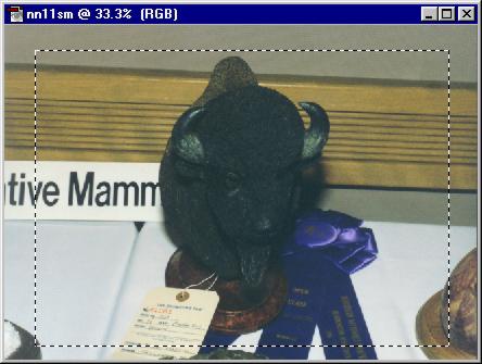
 Step 5: Resizing your image. Here you can see
the menu selection and the dialog box that comes up after choosing it. The cursor is in
the "Width" box, where I've changed it to 200 pixels like I did to all of the
other thumbnails on the same page. BTW, I used 800 for the enlarged versions. Now all my
thumbnails and subsequent enlarge photos will be the same size and aspect ratio when they
display in by browser. Notice that I have the "Constrain Proportions" and
"Resample Image" boxes checked (BTW, use Bicubic or "best" resampling
if you have that option). If you had scanned your photo at a higher dpi (like 150) that
what you want it to display at, this is the time to change that too. Be aware that your
photo may degrade (read blur) slightly if you resize it several times, so try to do
everything you need to do in this box at once.
Step 5: Resizing your image. Here you can see
the menu selection and the dialog box that comes up after choosing it. The cursor is in
the "Width" box, where I've changed it to 200 pixels like I did to all of the
other thumbnails on the same page. BTW, I used 800 for the enlarged versions. Now all my
thumbnails and subsequent enlarge photos will be the same size and aspect ratio when they
display in by browser. Notice that I have the "Constrain Proportions" and
"Resample Image" boxes checked (BTW, use Bicubic or "best" resampling
if you have that option). If you had scanned your photo at a higher dpi (like 150) that
what you want it to display at, this is the time to change that too. Be aware that your
photo may degrade (read blur) slightly if you resize it several times, so try to do
everything you need to do in this box at once.
 Step 6: Sharpening (not tool sharpening either guys).
Now you can finally sharpen this photo up a bit, so it looks good. In case you've ever
wondered, almost all scanners cause your photos to be slightly blurred. So this is a
necessary step to having great looking pictures on your web site. Notice that I'm using
"Unsharp Mask", and not one of the other sharpening methods. This is because
these other ones are "preset" defaults of the program, and are best used to
sharpen vector graphics or B&W pictures. Unsharp Mask also gives you a high degree of
control over the sharpening process, which can make a difference depending on several
variables. The first field in the dialog box is "Amount". This field can
generally be set anywhere from 150 to 220%. In other programs this field may be called
"sharpness amount" and may be on a different scale than PhotoShop. The second
field call "Radius" determines how far around each pixel the sharpening filter
goes when sharpening. It is usually set anywhere from .9 to 2 (I
Step 6: Sharpening (not tool sharpening either guys).
Now you can finally sharpen this photo up a bit, so it looks good. In case you've ever
wondered, almost all scanners cause your photos to be slightly blurred. So this is a
necessary step to having great looking pictures on your web site. Notice that I'm using
"Unsharp Mask", and not one of the other sharpening methods. This is because
these other ones are "preset" defaults of the program, and are best used to
sharpen vector graphics or B&W pictures. Unsharp Mask also gives you a high degree of
control over the sharpening process, which can make a difference depending on several
variables. The first field in the dialog box is "Amount". This field can
generally be set anywhere from 150 to 220%. In other programs this field may be called
"sharpness amount" and may be on a different scale than PhotoShop. The second
field call "Radius" determines how far around each pixel the sharpening filter
goes when sharpening. It is usually set anywhere from .9 to 2 (I  find 1.2 or 1.4
effective enough for me). The next field is called "Threshold", and determines
the threshold of the filter where it should and should not sharpen (you don't want to
sharpen a large monotone area of the picture). Effective range on most photos is 5 to 20
(I prefer to keep mine at 9 though). Remember not to over do it when sharpening your
photos (300% sharpening rarely looks any good). If you start out with a good looking in
focus photo, you can usually stick with settings similar to what I have shown here.
find 1.2 or 1.4
effective enough for me). The next field is called "Threshold", and determines
the threshold of the filter where it should and should not sharpen (you don't want to
sharpen a large monotone area of the picture). Effective range on most photos is 5 to 20
(I prefer to keep mine at 9 though). Remember not to over do it when sharpening your
photos (300% sharpening rarely looks any good). If you start out with a good looking in
focus photo, you can usually stick with settings similar to what I have shown here.
 Step 7: Saving your Pictures.
Sounds simple enough, just go File-->Save As, right? Well, not quite that easy. In this
series of steps I've shown you, its assumed that you are working with a scanned image of a
photo. Therefore the "recommended" file format to use is JPEG, and JPEG ONLY!
You may recall from step 1, that I had not checked the "Save Thumbnail" box.
When saving a photo for your web site, you shouldn't save a "thumbnail" inside
the photo either. Don't be tempted to use the "progressive" save option of most
photo editors either (it may look neat when downloading, but it makes for a larger file).
Also, a JPEG saved with the progressive may not be compatible with all programs,
especially with JPEG post production compressors like Cyberview. The reason I'm using the
"Maximum" quality value of 10 in this example, is because I intend to process
the photo through Cyberview (1.02 evaluation shareware version). Once you've save your
Photo in JPEG format, you shouldn't go back and edit and the resave it again, as it will
noticeably degrade each time you do it (that's why its called "Lossy"
compression). That is why I saved the original scanned file in a TIFF format. If I do have
to go back and fix something, I'd rather start with an unedited pristine photo and redo
everything, than use one that will degrade each time its edited and saved.
BTW, if you've looked closely at the properties of the pictures I'm using
in this tool tip, you'll notice that they are 3 bits per pixel GIF files (that's why the
"photographic" parts of some of them look lousy). These types of files, that
have only a few colors, are excellent candidates for the GIF file format. Others include
very small icons, seen on most web sites, animation, or very small photographic thumbnails
(under a inch square usually).
Step 8: More compression. To really make your
JPEG photographic files as small as possible, get yourself a "super compressor"
program like Cyberview. Click here to see a screen shot, or here to see it in a new browser window.
Back to top
Nov.-Dec. Carving & Tool Tip
On the various woodcarving newsgroups and list servers that I subscribe to, I often see
carvers asking for tips and/or plans on building or buying a dust collector (bench top or
laptop). The first question that is usually asked by carvers is "How expensive is
it?". Because a dust collector is (IMHO) a safety device, the first question asked
should be "How good is it at filtering dust?", and the second question should be
"Performance?", and only then should "Cost?" come into the buying
decision. You can't put a price on your health and safety, and why have a "Yugo"
when you can have a decent one with three or four times the performance, for just a little
bit more money. In fact, I started writing this article as a reply to someone's request
for information on "inexpensive dust collector" plans, or ready made units.
Here are a few pointers (and a few things to chew on) for all the carvers
out there thinking of making their own home made dust collector, or looking to buy a ready
made commercial product. BTW, this article is geared toward "wood carving" dust
collection systems, but most of the basic things still apply to ducted shop models (used
for table saws and such).
Safety First!
If your going to make a home made dust collector, use an "INDUSTRIAL" grade
mechanical filter. The filters in most hardware stores and such are made for filtering the
ambient air in your house, not for stopping even moderate amounts of wood dust. I refer to
these types of filters as "leaf catchers", because that's all they'll filter
out. In fact, most are rated at; or less than 10% efficiency @ 10 microns when used within
their airflow specs (and most aren't being used within spec). A good industrial filter
should be capable of 97%+ efficiency at 3 to 5 microns, and 30%+ efficiency @ 1 micron.
They cost a little bit more, but are well worth it. Remember, the idea is to
"collect" the majority of the dust (hence, filter it out of
the air), and not just recirculate it into your work area and lungs. By the
way, always use a filter that has a CFM rating equal to, or above, that of the fan(s) that
your unit will have in it (even an industrial filter will be
"useless" if you exceed the maximum airflow efficiency ratings by more than
10%).
Don't get sucked into using an "electrostatic" type of filter either (washable
or other types). I almost did once myself, because the "ASHRAE 52.1-1992"
test sheet (here after referred to only as "ASHRAE")
initially looked very good. I then asked the technicians at the company who did the ASHRAE
testing a few important, and pointed, questions about how the test is performed and what
some of the more obscurely named measurements meant. I found out some very interesting
facts on how the tests are conducted, and how the report itself can be used somewhat
deceptively to quote "efficiency".
Although electrostatic filters can claim a very high percentage of dust collected
"initially", this one was even rated down to the sub micron level, they
cannot hold very much of it. The 24"x24"x1" filter that was used in this
test example (which claimed near HEPA filtering @ 1200 CFM), could only hold 60 grams (
2.1428 oz.) of the synthetic dust that they used for testing (not very much by wood
carving standards). Initially, for the first 10 to 15 grams, the filter was filtering
at near HEPA quality. After which, its "efficiency" dropped off dramatically.
The filter manufacturer had quoted ratings using one part of the "averaged"
summary data. Because the filter was working at near HEPA standards initially (the first
10 ~ 15 grams), it skewed that particular average in their favor. Obviously a filter that
has to be cleaned or replaced after you get more than a few tablespoons of dust on it, is
totally impractical for a dust collector. I myself think that the current ASHRAE test was
designed to test mechanical filters, which typically filter a better as you load
particulate upon them.
After the fibers on this type of filter becomes loaded or "saturated" with
dust, it starts to "shed" whatever dust tries to "cake" onto it,
letting even large particulate through it. These filters work by using the airflow to
induce an electrostatic charge in the filter media which is made up of two or three
different interwoven materials (usually polypropylenes) that have different dielectric
strengths. But when the media fibers becomes coated with dust, they no longer work at all.
Even moderate sanding of your carving would saturate this type of filter up in a couple of
minutes of usage, after which, the rest of the dust would go right through it.
I can't stress it enough! Stay away from so-called electrostatic filters!
Designing for filter efficiency and
performance
A generally good dust collector design has the filter before the fan(s). This is
because it is much easier to push particulate (dust) "through" any given filter
media (not a good thing), than it is to suck it though any given filter media. To see this
for yourself, take apart the heating and return ducts in your house. You'll notice that
the return duct is dirty, while the heating ducts are much cleaner. This is true even if
you didn't use a furnace filter at all, because dust will settle quickly in a vacuum (return
duct), and won't settle in a high pressure air flow (heating ducts). With these
basic physics in mind, its easy to see that a given dust particle will have more of a
tendency to "drop" onto a filters surface or interior fibers when in a vacuum,
than in a pressurized environment. This is why you'll see a "puff of dust"
coming out of most bag filters when they are first started up (not to mention what you
can't see during operation, because the air flow moves the dust too fast to be seen).
It has been said (even by a few bag type manufacturers themselves), that the filter
efficiency doesn't come up to spec until there is a coating/caking of dust on the interior
of the bag (technically, their letting the dust do the actual filtering). All
mechanical filters get more efficient as dust loads onto them, but bag type filters seem
to rely too much on an initial dust film to work properly.
Putting the filter behind the fan(s) also retards the efficiency of most fan designs
that I've seen (up to 50%, depending on the fan design/type), because of back pressure and
turbulence this causes on the trailing edge of the fan blades. Another advantage to
putting the filter first, is that it keeps the fan blades clean so they operate at their
best efficiency (and you don't have to worry about dropping any large chunks of wood
into it either). Also, when setting a filter before the fan(s), you'll want to keep a
couple of inches of space between them, so the fan doesn't suck air through only one spot
on the filter (Not doing so, can render a filter's efficiency rating
"useless").
So why would anyone make a unit with a bag filter behind the fan(s)?
Because its allot easier to design! This is because in a "filter before the fan"
design, you have to design the whole unit around the filter's size and CFM ratings (and match it with the right sized fans with enough CFM & static pressure);
if you want to make it portable (if you don't do that, it probably won't be very
portable). Obviously, a bag filter can be almost any size you need it to be, as it is
"external" and does not need to be placed in a housing of any sort.
Some more interesting "filter
physics"
Generally speaking, the higher the surface area ratio of a given filter, to the unit's
airflow ratio, the better its filtering efficiency will be at a given air flow (CFM).
Simply put, if your using a filter designed to filter out 98% of 5 micron sized particles
at 700 CFM, and the unit is capable of 700 CFM of airflow, then 98% of 5 micron particles
and larger should be stopped. If you run the same unit at only 350 CFM, the filter
efficiency increased dramatically, even getting the majority of sub micron particles (filter efficiency ratings are usually only quoted at the filter's
maximum CFM rating).
This is where having a dust collector capable of variable speed is important. When
doing rough out work on a carving, the types of carving bits used for this generally
generate large volumes of larger particulate (I really can't see using a fine sanding
drum for doing initial roughing out), most of which a good filter media should be able
to handle even at its maximum airflow ratings. When sanding and doing detail work with
finer bits/tools, you are generating allot less volume of dust, but usually much smaller
particles. You should turn down the speed of the collector at, or just a little above,
what is needed for adequate dust collection/removal, so that the filter media will then be
capable of collecting the finer dust that detailing and sanding generate. Cleaning
out the filter before using the unit again at higher speed levels is only prudent, as the
smaller particulate would may get pulled through the filter if turned up high again.
This is also where bag filters have problems. The dust film on the
top of the interior will have a tendency to fall off, because of the drop in pressure,
which then lets a good deal of the smaller particulate through the "filter"
media.
Focusing airflow (A.K.A. venturi
action)
Obviously, using a smaller opening (smaller than the box or filter dimensions) where
the dust is to be collected at, will give it better drawing power, because it speeds up
the flow rate of the air at the "inlet" point (which is known as Venturi
effect). The size of this opening is somewhat dependent on the fan(s) CFM, diameter,
and how much "static pressure" it can pull (AKA: inches of Water Gage). The idea
behind designing a good venturi flow in a dust collector is to get A:
Laminar airflow, & B: speed up the airflow
speed at the inlet (effective CFM).
Laminar airflow means that there is little or no turbulence at, or behind the inlet
(the opposite of turbulent airflow). Cutting a hole in a board (and sucking air through
it) will cause high instances of turbulent air flow around the inside edges of the inside
of that hole, which in turn cuts the efficiency of the units effective drawing power
because it is constantly fighting against that induced turbulence. Instead of abruptly
focusing airflow, I like using "side panels" or shields, of some sorts, to
gradually focus the airflow, so that any one given side panel is not angled more than 44
degrees relative to the direction of the airflow. For a fan(s) with good WG specs (.5 or
better), a ratio of 1.5 to 1 (inlet area : fan area) down to 1 to 1 is ideal.
Gradually focusing the airflow also disperses the dust particulate more evenly over the
the filter's surface. Ribbed flexible hoses should also be used only when needed, and then
sparingly, as their uneven interior disrupts airflow and causes pressure drops because of
the excess turbulence they produce.
Effective CFM Example: You have a 10" diameter fan (inside diameter of cowling
or exit port), that can draw 600 CFM. Its cowling or exit port "area"
(area = pie * (radius squared)) is 78.5398 sq. inches. To get an
"effective" air flow speed of 600 CFM at your inlet, your "ideal"
inlet opening should be about 78 sq. inches of total area, (which, BTW, is a 1:1 ratio).
If however your inlet opening has 117.81 sq. in. of area, then your ratio will be 1.5 to
1, and your "effective CFM" at the inlet will only be about 400 CFM. Having an
inlet area smaller than your fan(s) (exit port) area, can cause some fans to loose some of
their static pressure and airflow speed, unless the fan(s) have a somewhat high static
pressure specification. If you don't focus the airflow, a unit rated at 600 CFM, will act
more like 200 or 300 CFM.
Why not use a filter that is about the same size of the fan, because then
you wouldn't have to refocus the airflow? Well, in a perfect world it would be the ideal
solution. Unfortunately, filters only come in certain "standard" sizes and
shapes. And even though industrial filter lines have far more different sizes than
standard filters found in hardware stores, there are still physical limitations that
apply. In other words, the filter is usually the biggest thing, and everything else is
designed around it. Of course a "custom made" filter would work nicely, but then
you'd probably be shooting yourself in the foot as far as cost is concerned.
All the world's a stage (all you
need are "good fans" to perform)
Fans capable of at least .5 inches of static pressure or better are desirable for any
dust collector, but it is not the "end all be all" of fan specifications. A
vacuum cleaner has very high static pressure ratings (suction power), but has
nothing for CFM (airflow speed). Conversely, a standard box fan usually has a
fairly reasonable CFM rating, but the static pressure ratings for these are sometimes
dismal.
So, how do you choose a fan?!? Well I've always liked "tube axial" fans
myself, because they usually have good static pressure ratings, high CFM, and compact
design. Generally, high CFM fans (200+) of this design usually have better static pressure
ratings when they have more fan blades (5 or 7), than they do with less (3). Of course,
there are "dogs" out there of this variety too. Stay away from anything that
looks like it may have once been used as an oscillating fan (rounded
fan blades, usually white in color, shiny flexible fan blades). The better ones
are the type used in mini and mainframe computers for cooling, where high airflow in a
compact design is imperative (usually a black aluminum
frame/cowling with mounting tabs, 5 or 7 blades, fan blades are very stiff, the outer
edges of the fan blades have square corners, and come within 1/16th inch or less of the
cowling).
It has been my experience that most "squirrel cage" type blowers don't have
enough static pressure or air flow, until you start scaling the size up considerably.
Furnace blowers are nice, but not very portable. I don't think you'll ever see a
commercial "portable" bag type collector with a squirrel cage type blower that
is over 1000 CFM, unless it comes with its own dolly cart.
If you happen to use a furnace blower to make a homemade dust collector,
do make sure that it has ball bearings instead of sleeve bearings (some
newer furnace blowers use sleeve bearings, which wear out within a couple of years).
Other Misc. Notes
Its been said "the devil is in the details". Air leaks can be like little
devils, robbing your dust collector of performance and filtering effectiveness. When
building or buying a dust collector, make sure it has things like filter gaskets (which
keeps air flow from going around your filter), and that any air focusing panels or
shields (or the main housing itself) does not have excessive gaps where air can
leak through.
One thing I "hear" allot about, is the concern of how loud a dust collector
will be. Unless the unit's fan(s) are unusually loud, my experience has been that if your
working with a tool that requires you to run the dust collector at full speed (like a
1/4 hp flex shaft Foredom), then that tool alone will usually generate enough noise
to warrant using hearing protection any ways. If, on the other hand, you are using a small
micro motor tool; turning down the speed a little on most commercially available dust
collectors will keep the noise levels down to a minimum, while still having enough drawing
power to collect the smaller amounts of dust a tool like that generates. Other things you
can do to reduce noise levels are things like not having the collectors fans within close
proximity of a wall, as the wall will reflect noise. A rubber mat under bench top models
will keep low frequency vibrations from being transmitted to your table top. Rubber
gaskets between the fan housing and whatever it is mounted to prevents vibration from
being conducted to the rest of the enclosure (and may give you a better air seal
around the fans also).
When making/designing a ducted type of collector, use two 45 degree corners to take a
90 degree turn, otherwise you'll have an excessive pressure drop occur on that duct, and
possibly have it clog up at that 90 degree junction. Proper grounding of PVC ducts is
essential, as you don't want a static spark blowing you and your shop into dust too.
Another "rule of thumb" for running air ducts is, "the bigger the
better". A larger diameter pipe will have less of a pressure drop then a smaller
diameter pipe of the same length. To increase airflow at the end of each duct (the point
of usage), use a slightly modified pipe reducer to make the inlet opening smaller. The
inlet furthest away from the actual collector (or has the most pipe in between), will
generally have the weakest suction. So keep that in mind when deciding which tools should
go where, and while designing the duct layout also.
Back to top
July ~ August 1999 Tool Tip
This month's topic is about pyrographic
"systems", theory and application.
If you've seen all the ads out there for pyrographic systems, your probably a bit
confused about what makes a good unit, and the differences between different brands.
First, a little remedial theory on how modern "wood burners" work.... The
power supply: All modern units pretty much use the same principles and have similar parts
to them. The heart of the unit is the transformer, which is basically a 110v to 2v step
down transformer. In other words, it "transforms" a higher voltage to a much
lower "usable" voltage, which is used to heat up a small nichrome element at the
end of a burning pen. Although the transformer only puts out a few volts, most brands use
transformers that are capable of putting out upward of 20 amperes of current. To control
how much voltage and amperage a given transformer of this sort puts out, modern units
employ a triac or quadrac circuit. The circuitry is similar to a dimmer switch, which runs
in series with the voltage supplying the transformer to vary the voltage given to it.
Originally a "reostat" was used to do this, but they have drawbacks including
voltage drift due to the reostat heating up. Also, a reostat is not very safe, unless the
unit uses the proper fuses to prevent short circuit conditions from causing a fire. If
your circuit, transformer, and nichrome tips have been properly matched, your pen tips
should heat up throughout the power supply's "range" in a fairly linear fashion.
If not, it may go from running your tips from too cold to too hot in just a few degrees of
the adjustment knob.
I hope by now that wattage is finally a dead issue with most people "in the
know" (see Woodcarving Illustrated's "Power Carving Manual"). However, some
companies still persist perpetrating dubious claims of high wattage as a marketing ploy to
the new or unsuspecting potential customers. The amount of wattage any given power supply
is "capable" of drawing from a wall socket is a mute point, when you consider
the fact that if you were to actually get that kind of wattage to most pen tips, the tip
would last about as long as a cracked light bulb (bright, but short lived). Not to mention
the fact that you'd have to have a 12 or 10 gauge pen cord wire to be able to do it
(rather bulky, akin to car battery cables). Any unit rated over forty watts by the
manufacturer, is most likely being "rigged" by some abnormal means to get the
power supply to develop that much wattage draw. Our forty watt unit, for example, can draw
upwards of 70+ watts; if you dead short out the secondaries (output side) of the
transformer with a big chunk of copper, but that is hardly a useful benchmark in a real
world environment. In the real world, most pyrography texturing or burnishing that is
done, doesn't use more than twenty-five watts out of most systems. Light texturing usually
only draws about ten watts or less.The other parts of any modern pyrography unit are the
pen cord, the pen body, the actual heating elements the pen tips, and how they are
attached to one another.
One might think that there can't be much differences between different brands when it
comes to the power cord carrying power to the pen. Actually, this can make or break a
unit's ability to deliver proper heat recovery at the pen tip. The type of jacks used on
each end of the cord, to even the type of insulation coating the wire, plays a big part in
how much amperage is delivered to the actual pen tip itself. If the cord or modular
connections used (jacks) can't deliver the amperage, it makes no difference how much
wattage a given power supply is "capable" of outputting. A tell tale sign that a
given unit has a deficiency in this area, is if you can feel the modular connection at the
power supply (jack) warm up after a few minutes of operation. Every burner's cord will
heat up to a certain extent, depending on the operating range you are using (high or low).
The key is how fast the cord insulation can dissipate the heat. If you can feel the cord
heat up faster on brand A than on brand B, brand A "may" actually be doing a
better job of dissipating the amperage induced heat in the cord wire (if the two units are
employing the same sized gauge of wire in the cord). Obviously a bigger gauged wire in the
pen cord will be able to deliver more amperage to the pen. It has been my experience, to
get "really good" heat recovery, the pen cord wire should be one gauge size
larger than the pen tip nichrome wire being used. This is because as a rule of thumb; the
more metal in the pen tip, the more power it will need from the power supply to heat up
properly.
The way that the pen body and pen tips are attached, has been of some serious
contention among different manufacturers for some time. Some manufacturers have for years
staunchly supported using replaceable tipped pen bodies, claiming they were just as good
as a fixed tip system. Although many of these companies, as recently as a few years ago,
have started to offer fixed tipped pens to their customers. Why has this happened? Maybe
because customers were able to see the difference in heat recovery between fixed tipped
and replaceable tipped pens? Having a connector that close to a high heat source is bound
to cause problems, both electrical and mechanical in nature. "Surging" and poor
heat recovery occur in replaceable tipped systems after time, because of mechanical wear
of the connection, which is only sped up by heat. How fast this happens depends on how hot
you burn with them. While most burners out there have some sort of modular connection
(jacks) in the cord, these connections have a relatively large surface area. Replaceable
tipped systems out there have very little surface contact area at that particular modular
connection, which makes it a bottleneck.
Okay then, now that everyone makes a fixed tipped pen, which brand of burning pen you
buy is irrelevant. Right?
Wrong! If a manufacturer won't replace the tips on their fixed tipped pens after the
warranty is up, it is most likely because they have used an inexpensive, but inferior,
method of affixing the nichrome pen tip to the brass carrier of the pen body. This
inferior method is done by first crimping the brass carrier to the nichrome tip wire, and
then using a common lead and tin solder to weld the tip into the carrier. The first
problem with this method is that over 370~400 degrees, the lead and tin solder detaches
(melts actually) from the nichrome and/or just oxidizes away, leaving only the contacting
area of the crimp to deliver the power to the pen tip. This is why you can't solder with
this type of pyrography system, because lead and tin solder will bead off nichrome when
the nichrome is hotter than the solder. lead and tin solder only wets/sticks to copper,
brass, and a few other metals at higher temperatures. The second problem with this method
is that you can't replace the tip, because it is crimped into the carrier. If it weren't
it would fall out, or get pushed in, when the lead and tin solder melted. The proper way
to affix a nichrome tip to a brass carrier is by using a "jeweler's grade"
silver solder to weld the nichrome tip the to brass carrier. This type of solder has a
melting point over 1300 degrees, and adheres to nichrome much better. This is a more
expensive and more time consuming method for the manufacturer, as it does require a micro
oxy blowtorch, a steady hand, and years of experience. The only drawback to using this
method is that your pen bodies have to be designed, from the ground up, to handle the
extremely high temperatures that a mapp gas and oxygen torch can generate (and do it
repeatably, for tip replacements). So a plastic pen body is out of the question. Other
things about how the internal parts of the pen are designed, manufactured, and materials
used; can make a big difference how much amperage can get to the tip, as well as longevity
of the pen body itself.
Okay, lets talk about the actual nichrome pen tip itself. Not to much difference here,
nichrome is nichrome. Well, to some extent that is true. Some grades of nichrome do polish
up better then other grades do. If your picky, it can make a difference. Our pens are
highly polished from the factory, and ready to use. This is because a long time ago the
owner of SMC had noticed how much smoother and easier a polished tip acted as it was used
to texture various woods. Because the surface of the pen tip is very smooth, it glides
through the wood easier than a non-polished tip would. Different brands use slightly
different nichrome alloys, and some even use an alloy which has a good portion of cobalt
in them. This can make a difference in not only how well a nichrome tip will polish up,
but also its mechanical strength, and what its heat curve is like. While tip wire with
cobalt in it does exhibit good mechanical strength characteristics, it has a somewhat
non-linear heat curve, and it is very hard to get it to polish up as it likes to
"pit" during usage. This is why I had earlier included the pen tip wire, when
talking about parts of a pyrographic system that should properly be "matched".
This is also why I refer to a burner as a "system", as each individual part of a
given unit has to work as a system to function properly. You can use our pyrography pens
and/or cords on another brand's power supply, and they will work as good as or even better
than that brand's pens. But, they do work the best when using them on our power supply and
cords, as each component was built as a part of a total system.
One might think that the larger and/or longer the tip wire is, the more heat recovery
it will have do to its larger mass. Not as true as you might think. I even used to think
this was the case myself not that long ago. The theory goes like this: Nichrome, being a
natural electrical resistor, is also a natural heat resistor as well. So heat will not
travel extremely fast from one part of the tip to the other. The uniformity of the pen tip
(to a certain extent), and the supply of amperage it has available to it, play the biggest
parts in how well a given pen tip will perform during usage.
Although a nichrome tip will seem to heat up almost instantly when you first turn on a
given unit, you should be aware of a few things. When a nichrome pen tip first heats up, a
good portion of the heat that it is generating is being sucked up by the brass carriers
that it is attached to (replaceable or fixed tipped systems). So you should usually wait
about a minute before using it, to give it a chance to "normalize" the
temperature differential between the nichrome and the brass carriers. Then, if everything
else is working up to snuff, the pen tip should give you good heat recovery in most
situations. This particular phenomenon actually becomes more pronounced in "really
efficient" pyrography systems, and should not be confused with "surging".
Surging is when your pen tip goes from hot to cold, and back again, repeatedly (which is
caused by a "loose", corroded, or moving connection). This phenomenon is
different in that your pen tip will get a bit hotter while using it if you did not let the
pen warm up properly first, but it will not cool off again until you turn down the power
adjustment knob on the unit. This effect sometimes makes people mistakenly think that
there is something "wrong" with a pyrography system that exhibits this property,
or that the adjustment knob was moved after they started burning, or that the power line
is fluctuating the voltage supplied to the power supply. Some carvers, who are used to
using an inefficient pyrography system, may try to blow on the tip to cool it off right
before using it when they see this is happening. That trick doesn't work on a truly
efficient pyrography systems, as it will heat up the pen tip nearly as fast as you can
cool it off.
One quick way to test the efficiency of a given pyrographic system is to turn the unit
up to its highest setting using a blade like pen tip, and see how long it takes the tip to
attain its brightest glowing red color. An efficient unit will be faster at doing that,
than an inefficient unit using a similar sized pen tip. Next, using the same blade like
pen tip, put the side of the pen tip (not the blade edge) onto a piece of soft wood and
burn a trench with it. On a truly efficient pyrography systems, you will see the part of
the pen tip that is "in the wood" dim slightly for a moment, and then get red
hot again. You may need to lightly blow away the smoke this test causes, to actually see
this happening. If the part of the tip that is outside the wood stays red, but the part
that is in the wood does not glow red again during the test, it is a sign that there is a
bottleneck somewhere between the transformer and the pen tip.
Getting the amps to the nichrome tip "efficiently" is what sets ho-hum
burners apart from real performers. Amperage is king in this application! ANY bottlenecks
between the output side of the transformer and the actual nichrome tip, will cause poor
heat recovery performance in the tip. I like to use the analogy of sand running though a
pipe, where each grain of sand is an electron. (not water, because like electricity sand
would heat up the pipe when moved at a higher pressure rate, especially though
bottlenecks). Imagine a three inch pipe with sand being moved though it. If the pipe then
turns into a one inch pipe and back again to a three inch or even a four inch pipe, the
sand after that "bottleneck" will only have the same flow rate as it did in the
one inch section of the pipe (even though the pipe has gotten bigger again). If you
increase the pressure pushing the sand through the pipe (similar to raising the voltage)
the pipe gets hotter, especially in the one inch section. The hotter your pipe gets, the
more friction it has, and this too can slow down your flow rate. So you need to have a big
pipe to begin with, and not have any bottlenecks anywhere in it.
One thing that I see, every now and again, is a carver who thinks his pen isn't giving
proper heat recover, but in reality they are using the pen tip improperly or has the wrong
pen tip for the application. An example of this would be using "just the point"
of a large skew (knife like shape) pen to draw long evenly burned lines into their
carving. Obviously, you should use the whole length of the blade to do long evenly burned
lines. Although even the best pyrography systems can give "near instantaneous"
heat recovery, nobody has as yet come up with something that is truly instantaneous. A
ball point pen can deliver ink instantaneously to a sheet of paper when you write your
name, so the speed at which you make each part of each letter doesn't matter. A
pyrographic writing tip, for example, cannot do the same. So you must keep the speed at
which you move the tip at a constant velocity to get evenly pyrographed letters.
Back to top
January
2000 Tool Tip
An easy way to make a lateral line on
fish carvings.
If you've used the #13 pen to make fish scales, you may have already figured this one
out, but here it is any ways.
To make a lateral line, all you need is a stylus of some sorts. I like to use an
unheated/unplugged #9 or #8 (either original style or HD, depending on the width and depth
wanted) Optima 1 pen to do this, but a dead writing pen (no ink) or regular carver stylus
will work just as well. You will notice that using a thinner stylus makes it easier to
crush a deeper line, hence that will cause it to raise even higher. You may have to
experiment a little to find what type of stylus works best for you on a given wood.
You do have to use a wood that will "uncrush" when re-hydrated. Most woods
work fine, basswood is excellent at doing this. One wood that doesn't work very well is
tupelo, because it's really a "gum" taken from the roots of the tree, and it
stays crushed. Test how well this technique works on a scrap piece from your carving
before doing it, in case the wood is unusually soft or hard (even if you've done it on
that species before).
You will need to do this to the carving when it is about 1/32 to 1/16 inch thicker than
when you do your fish scale pyrography on it. The thickness will depend mostly on how deep
you push the stylus, and the stylus width. Using a fine stylus (approx. .032 to .041
inches wide), make the lateral line by crushing the wood down with it. You may need to go
over it lightly the first few times, pressing harder each successive time until its depth
is as deep as you were you want the final surface to be during scaling. Be sure to make
the depth as evenly as possible. This is why I like using something like a #8 pen, as it
facilitates this more easily. Again, if you use a burning pen, use it unplugged and cold
(your crushing, not burning here).
After your done with that, your ready to start sanding. Sand the surface of the fish
down so that the bottom of the little trench/line you just made, is flush with the rest of
the surface. Be careful not to over sand. The line will still be very visible, and will
"look" like it is deeper, even after you've gotten the rest of the surface flush
to it. Use your fingers to "feel" when you've gotten it flush, as this will give
you a truer lateral line.
Now your ready to put your scales in. You should still be able to see where the lateral
line is. If not, you may have over sanded. Using a tip like our #13 pen to burn scales in
(see previous tool tips), or a "scallop" fish scale
tip, works fine with this technique. Using a "cupped" or fish scale
"replica" style tip may cause you to over burn your carving, and negate/ruin
your crushed lateral line. Obviously, using a punch or burnishing method of scaling will
not work, as you'll mess up the scales when you re-hydrate the crushed lateral line. If
you've ever handled a real fish before, you know that the scales on most fresh water fish
don't have a very deep texture to begin with any ways.
Now your ready to bring up your lateral line using either plain tap water, or a mixture
of water and isopropyl alcohol. The isopropyl and water mix is usually 50:50, and works
nicely because it evaporates faster. Splash it onto the carving liberally, using a towel
immediately afterwards to soak up excess liquid. You should only need to do this once or
twice at the most, letting your carving dry a bit between wettings. The lateral line
should re-hydrate and raise itself within an hour or less (usually within a half hour). If
your lateral line did not raise enough, or not at all, you probably over sanded it.
You may have to do some light sanding of the lateral line near the back end of the each
scale if it is raised too high there. Wait until your carving is fully dried (overnight)
before sanding or painting it. You will notice when using this technique that going across
the grain may require a thinner stylus, as the wood will be a bit harder to crush down.
Using too thin of a stylus when going with the grain on a porous wood may cause some
slight "splintering" of the lateral line after it is re-hydrated. Wait until it
is fully dried before trying to fix it.
Again, try this technique on a scrap piece of wood from the carving "going in the
same grain direction" as you will be on the carving, before doing it on your carving.
This will help you gauge how deep you'll have to crush it, and how thick of a stylus to
use, in order to get a satisfactory lateral line.
Back to top
October
2000 Tool Tip
Yet another way to transfer
patterns to wood.
One day whilst messing around in the shop, trying my hand at paper pyrography, I
accidentally picked up a scrap piece of thermal paper (a cash register receipt actually).
I put it on my table, thermal side down, and tried to get a light toasty brown on
it with a shading pen. Well, the thermal paper didn't work too well, as far as me
trying to do pyrography on it, as I soon got side tracked.... When I removed it from
the table, I noticed that it kind of wanted to stick to the table. Then I noticed
why.... Evidently the chemical that turns black on thermal paper, also likes to
transfer onto whatever you have pressed against it. Hmmm, I thought.....
Any ways, this eventually led me to develop a new way of transferring patterns onto
wood. Obviously, you can't use a laser printer or copier to put the pattern onto the
backside of the fax paper (heated rollers), so you need to use an ink jet printer instead.
If your pattern is out of a pattern book, you'll also need a scanner. Because
fax paper comes in rolls, you'll also have to cut it to length first (which is also nice
for doing long/large patterns).
Having a computerized version of a pattern is also nice, as you can use certain
graphics programs to add to, or erase, parts of them. The pattern below originally
had a bunch of quilted square blocks just underneath the girls boots, running two blocks
high and the length of the pattern. BTW, this is more of a "tole painting"
pattern than it is a pyrography pattern. I'm just using it here as an example.

After printing the above pattern onto the "backside" of some fax paper, I set
about transferring it to a small piece of birch board using a modified #9 writing tip (end
of the tip is symmetrical). You'll want to trace the pattern lightly with your
heated pen, using a low (possibly lowest) setting on your burner. Below is the
transferred pattern on my birch block (yep, I did a little burning on it already too).
Erasing the pattern, or parts of a pattern, was a bit more problematic at first.
An eraser doesn't work, and sandpaper is too labor intensive.... Heat from a pen, if
it's high enough, will pretty much get rid of pattern lines; but that doesn't work on
every part of every pattern. The solution is to use lacquer thinner (acetone may
work also), either as a wash after your done pyrographing your pattern, or with a Q-tip
when "fixing" parts of a pattern prior to burning it.
You might notice that the "o" in the word "of" on the fifth line of
text is missing, as well as the right side of the upper patch on her dress. This was
done on purpose. I had originally transferred both of those items to the wood.
I just took a Q-tip and dipped it into some lacquer thinner, took off the excess so
it didn't spread out too much, and used it to "erase" those two parts of the
pattern.
One nifty thing about this method is that it makes the pattern sheet stick to the wood
a little bit. So as long as you don't pull the paper away from the wood, at least on
one edge of the pattern, you can pick up the edge of the paper to see where you might have
missed.
Now I printed my pattern with black ink onto the backside of the fax paper. You
might try printing your pattern with a lighter color like cyan or even yellow instead, as
you should be able to see what parts of the pattern you've gone over without ever having
to lift up the edge of the pattern up at all (most fax paper is pretty thin stuff, and can
be easily seen through).
Now if I only knew what that chemical they use to make fax paper with is (or something
similar), I could fill an ink jet cartridge with it and just use an iron for really quick
pattern transfers. Please drop me a line if you happen to know the answer to that
one.
Back to top
December
2000 Tool Tip
How to make fuzzy
hair, for my teddy bear.
You may remember seeing the pattern below in last month's tool tip, where I discussed a
new method for transferring patterns to wood. I happen to take that same piece of
wood with me to a craft show a few weeks back, and sat down to finish it.
I outlined most of the girl, and even the teddy bear, but then realized I
hadn't thought out how I would make the bear look fuzzy (Doh!). The picture below is
what I came up with. As this was a "direct" scan into my computer, you
can't really see that the wood on the teddy is actually raised up a bit above the rest of
the surface (yes, you can even feel it).
I had heard this tip a few years back from a good customer of mine at a
carving show, and after using it myself, found that it can be quite useful. This
technique is done using a #5 "Spear Point" burning pen at a medium low setting.
Each piece of "fur" is put in somewhat randomly, as you don't want a
pattern to form (don't do each hair in a row).
.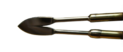
Photo of #5 Spear Point pen tip
As the first graphic below illustrates, you need to use the pen with the
flat/wide side of the pen tip facing your wood at a low angle of attack. Just jab
the pen tip in a little bit, not much is needed (1/32" to 1/16th") You
also need to go "with" the grain when doing this. Also, when you cut wood
with the grain, and it tends to rip up more when going one direction than it does when
cutting it in the opposite direction. That is because the grain is also going downwards
into the depth of the wood (so it tends to rip up more). This is also the direction
you may want to go when doing this, to get a more pronounced effect.
After pushing the end of the pen tip just under the surface, quickly twist
your pen body 20 to 30 degrees in one direction or the other. This helps add to the
"random-ness" of your raised fur, as some will be twisted one way, and some the
other way. You might want to experiment when doing this, as you may be able to get
fur that is on the side of a bear's face (for example) to be lighter or darker in some
areas by just twisting your pen in only one direction in certain areas.
As illustrated by the the graphic below, you can get the fur to stand up
more by raising the back of your pen up, so that your pen is at 40 to 50 degrees right
before pulling it out. After a bit of practice, you'll find yourself twisting,
and and raising the back of the pen, at the same time. This is perfectly normal and
is how I tend to do it also.
You, and maybe others around you, may see how furry this technique makes
your subject look, and may want to feel it (DON'T). The picture up above had much of
its fuzziness removed because I mistakenly let people around watching me feel it. If
you do feel it, do so very lightly. A good finish on your pyrography after your done
should also keep individual "hairs" from falling out (because it's fuzzy
looking, people will tend to touch that part of it). Also, if you pack up your
finished work for travel, make sure nothing heavy is on top of it.
In case your wondering, the insides of the bears ears, and the patches at
the end of the feet and arms, were done by just dotting the wood with the #5 pen at a 90
degree angle (a kind of pointillism). The dress, smock, shoes, and ribbon were done
using the #13 shading pen (medium), the girl's hair and socks (including stitching on her
patches and teddy bear) were done using the #12 small rounded blade pen, and the pattern
was outlined and dotted (eyes, dots on dress) using the new #9 modified pen tip.
January
2012 Tool Tip
Total cost of ownership (TCO)
or
( how much does that tool "really" cost?)
When people shop for tools, especially for what have been traditionally
expensive tools, they tend to shop around to get the best price. If you can get the
same, or similar, tool at XYZ company for 40% less than what ABC company is selling it
for, why wouldn't you?
Well.... Sometimes you have to read the fine print, and should maybe
ask a few pointed questions. Like: what is included with the tool? What the
warranty is, what does it actually cover, and for how long? You might even
want to know the cost of "out of warranty" repairs (would you be better off just
buying a new one when this one has a minor problem in a few years?). Does the
manufacturer have reasonable rates for non warranty repairs? Do they even repair
them, or do they just sell replacement parts and expect you to repair it yourself?
These questions should all be asked during the buying process, if you plan to have the
tool for any reasonable length of time.
For example: Recently, I seen one of our competitors selling a
similar micro motor handpiece to the Optima 2 Plus for a seemingly much lower price.
This is obviously being done to drive their competitors out of the market place, so
they can then jack up the prices again later on, as all of their other handpieces are
still at relatively much higher prices. Well, low and behold, that handpiece only
includes one collet ($22.00 more for a second collet), and no extra brushes ($12 more,
their price). Okay, but that only accounted for a $34 difference. What about
the rest of the price differential? Well, the warranty on the power supply is only a
year (ours is lifetime), and the warranty on the handpiece is only for six (6) months
(ours is two years). Finding their warranty on their web site proved somewhat
difficult, as I ended up having to google their site for the word "warranty".
Specifically, their warranty says: "HANDPIECES – These products are under
warranty for a period of SIX MONTHS from the date of original installation by the
purchaser. IT DOES NOT COVER MISUSE, NORMAL BEARING, OR CARBON BRUSH WEAR."
Okay, misuse (obviously) and brush wear (considered a consumable) are
understandable, nobody's warranty covers those two items. But what about one of the
main, and arguably the most expensive, components? Bearings! Other than
brushes (again, considered a consumable), they are THE main parts of a micro motor
handpiece that is going to wear, and eventually they wear out and need to be
replaced. If properly designed, with the proper lubricant, proper installation, and
barring any misuse, bearings can last for thousands of hours. They generally are not
considered a "consumable" like brushes are. So what do they mean by
"normal bearing wear"? More to the point, what do "they"
consider "normal"? I think the six month warranty speaks volumes as to
what they consider "normal" bearing wear.
Here is a simplified example, to give you an idea of what that means.
Normally, most manufacturers calculate the MTBF or "Mean Time Between
Failures", which is kind of like the "worst case scenario" expected
lifetime of a piece of hardware, component, or device as a whole. Then divide that
by at least two or three (possibly higher), and then use that resulting number as the
basis for their warranty and/or price (again, this is a simplified example of a much more
complex calculation). That way, they do not have to replace or repair hardly any of
the products that they sold in the past under warranty. Understandable, as companies
are in business to make money, and most can't afford to replace or repair even one
tenth (1/10) of their previously sold products for free. But what this should be
telling you, is that with a 6 month warranty, they assume that a significant amount of
their handpiece bearings WILL START TO FAIL within at least a YEAR or two! Hmmm, and
how much do those cost you ask? Well, just to buy the bearings and install them
yourself will cost $13.35 for each bearing, and at least another $6.50 for shipping.
That's $19.85 for one bearing! And there are four of them in each handpiece (not
including the collet thrust bearing which sees little wear). If you call them up and
ask about what it would cost to have them repair it, you will probably get an "hourly
rate" (usually north of $80 per hour for labor, not including parts) with no definite
estimate. In fact, it is not unusual for handpiece repair centers to charge upwards
of $120 per hour for labor alone.
By the way, our costs for out of warranty repair for handpiece bearings is
only $10 per bearing, plus ACTUAL shipping costs (currently $5.25 for a Priority Mail
Small Flat Rate Box). You should also note, that the warranty on our handpieces is
now two (2) years (since Jan 1st 2011), which include bearings (barring misuse, abuse, or
improper storage).
Well, you might be thinking that you can just buy the bearings from them,
and replace them yourself, to get by much cheaper. You'd be wrong! In
the long run, that will cost you even more. In fact, if you call me up and ask me to
send you replacement bearings, I won't sell them to you. Wait, what? Why?!?
Well first off, to do it properly you would need at least a half dozen of each bearing
size to insure that you are not putting on a bearing that is either too tight, or too
loose, onto the main shaft or motor armature shaft. The shaft OD's and bearing ID's
are rated at ABEC5 standards, which are specifically +0.0000" -0.0002"
tolerance. If you force a bearing onto a shaft, you will loose most, all, or even
more than the clearance inside the bearing (typically 0.0002" to 0.0005"
clearance, AKA MC2 specs) and the bearing will not last very long. Conversely, if
you put a bearing onto a shaft and it is too loose of a fit, your bearing will have
excessive runout, causing vibration, brinelling of the shaft and bearing race, excessive
bearing wear (because you are now running the bearing beyond the runout tolerance), and if
that loose bearing seizes it will cold weld itself to the shaft (ruined shaft = even more
money). I can't even get into the other methods that we use (proprietary, sorry
can't talk about it ;-) to insure that the maximum possible bearing life is
attained. But to put it simply, if you do not know the exact proper methods and
procedures used to install precision handpiece bearings; I can guarantee that even with
the best possible bearings that money can buy, you'll most likely ruin them upon
installation, or at the very least, significantly shorten their potential lifespan.
Having your handpiece repaired by a qualified professional can also head
off other potential problems, before they become a real liability. For example, if
your handpiece brushes are about to wear out, and you do not change them immediately, you
will dramatically shorten the lifespan of any bearing that is near the commutator ring,
and possibly incur an expensive armature replacement too. A conscientious
professional will always check the brushes (even if he/she is only working on the shaft
bearings), and should advise you to spring for the brushes if they need replacing, which
will save you money in the long run. If this is not spotted, and the commutator is
damaged, you will go through bearings (excessive heat) and brushes (excessive wear) like a
chocoholic through candy, and end up paying for an expensive new motor armature.
Unusual debris, or debris in the "wrong" places will also tip off a qualified
professional that you may be doing something wrong that can dramatically shorten the
lifespan of the handpiece bearings, and will advise you not to do that anymore (it might
sound harsh over the phone, but remember that this guy/gal is actually trying to save you
money).
Knowing all of this, your probably now asking yourself "if this is
true, then why would any handpiece manufacturer allow customers to change their own
bearings?". Well first off, they're selling you more parts, more often!
As my younger daughter would probably say... DUH!.... Either they don't know,
or just don't care, about what is required to install precision bearings into a precision
instrument like a micro motor tool.
Another question, a skeptic like myself might ask, is "how can you
charge so much less than your competitors for bearing replacement?" Well, we do
this as a service to our customers, not as a part of the business that needs to generate a
profit. Since fewer of our handpieces need repair any ways (mostly 5 to 6 years and
older is what we see), repairing handpieces is not a full time job.
So, lets compare them now shall we? After 5 years, assuming no
"in warranty" work was needed, the handpiece was properly maintained, and the
equivalent "in shop" repair by the Mfg. was done. The variability in the
least number of repairs and most number of repairs assumes that, all things being equal, a
significant number of bearing failures do not start happening until at least two to three
times the warranty period, and that average excludes "extreme users" that use
their handpieces a lot, inappropriately, or in an industrial environment (8+ hours per
day). In other words, average users. The "<<<1" means WAY
LESS than 1, or very unlikely (almost zero, this is taken from our own data). Also,
you should keep in mind that it is usually our policy to replace bearings in pairs instead
of individually, as one bad bearing on a shaft will usually cause problems for the other
bearing on the same shaft down the road (so it's actually cheaper to replace the so called
"good bearing" then, than having to ship the unit back and forth again in a year
or so for that previously "good" bearing to be replaced). So 1 would = 1
"set" of bearings (2 bearings). The "True Costs in 5 years"
column shows both the "Least non warranty bearing repairs" average and the
"Most non warranty bearing repairs" average, rounded up the the nearest whole
number (which, only mathematically, doesn't actually favor us).
| Manufacturer |
Initial Cost |
Warranty |
Least "non warranty" bearing repairs
in 5 years
(Low to medium usage, well taken care of) |
Most "non warranty" bearing repairs
in 5 years
(Medium to High usage, some abuse) |
True Costs in 5 years
(best case to worst case rounded up average) not your including shipping costs to the
factory. |
| A (Optima 2 Plus) |
$209 |
2 years |
Number of repairs ranges from 0 to
<<<1 (nearly zero)
Average = almost 0 (VERY unlikely to need a repair) |
Number of repairs ranges from 0 to <1
(unlikely, but possible)
1 (rounded up from avg.) * $10 (Bearing price, includes labor) * 2 (1 set) + $5 (shipping)
= $25.00
Expression = 1*(10*2)+5=25 |
Original cost + Repairs
$209 to $234 |
| B |
$135 |
6 months |
Number of repairs ranges from 1~3
Average # Repairs = (2) * $13.35 (Bearing price) * 2 (1 set) + $35 * 2 (Labor) + $6.50 *2
(shipping) = $136.40
Expression = 2*((13.35*2)+35+6.5)=136.40 |
Number of repairs ranges from 3~5
Average # Repairs = (4) * $13.35 (Bearing price) * 2 (1 set) + $35 * 4 (Labor) + $6.50 * 4
(shipping) = $272.80
Expression = 4*((13.35*2)+35+6.5)=272.80 |
Original cost + Repairs
$271.40 to $407.80 |
Keep in mind, that even if you had the same number of repairs on one of
our handpieces, your costs would still be less. So, if you use their "number of
repairs", but using "our costs for doing the repair"; the following shows
two expressions for best and worst case scenarios: Best case = 2*((10*2)+5)=50 + Original
Cost = $259 Worst case = 4*((10*2)+5)=100 + Original Cost = $309.
Given, this is a conservative estimate only using our data, as we do not
have access to our competitor's failure rate data. However, knowing how manufactures
determine price and warranty gives us a key insight on their expected failure rates.
Also, we called around to a few of our competitor's dealers, asking what the average
lifespan was on their handpiece bearings. The consensus we heard was about two
years, and that the labor costs were usually around a minimum of $35 per repair (bearings
& shipping is more). Therefore, I feel the above table should be fairly accurate given
the known variables. Keep in mind also, that there are also "certain
flaws" that we are aware of in our competitor's handpiece, which we know
causes most of their bearing failures (even though it may look identical to ours, it is
NOT).
After comparing the "total lifetime cost of ownership" of a tool
like the Optima 2 Plus, and our competitor's discounted micro motor handpiece, you should
realize that "cheap handpiece" is likely to cost you much more money than you
bargained for down the line. This of course doesn't even include your downtime (what
is your time worth to you?). What is also missing from this discussion is the power
supply. Their power supplies typically have a 1 year warranty on them, and I'm
guessing repair costs could possibly exceed the price of a new one. Our power supply
carries a lifetime parts and labor warranty, the most you would have to pay for is
shipping to and from the factory, and it is our policy to ONLY charge actual shipping
costs.
So, would you rather pay a little more up front for a micro motor
handpiece that is less likely to have problems, and lower repair costs down the road, or
opt for the super cheap handpiece that has a paltry warranty (an indication of poor
reliability), and higher repair costs?
October 2015 Tool Tip
Going, Going, Gone...
or
How to prevent your pyrographic art from fading
As many pyrographers know, UV will cause their artwork to fade.
While this effect is true, UV is not the actual "direct" cause, but
rather acts as a catalyst. Once you know the actual mechanism, you can now prevent
it from happening. I have told this story to many customers over the last dozen
years, so bear with me....
I had come across a discussion years ago, that took place on a
popular pyrograhic list server I had frequented, about pyrography fading, and what could
done to prevent it. During the discussion, someone mentioned that when ever she used
translucent oil color pencils on her burnings, they tended not to fade or fade as much as
they did without it being applied. Also, people had noticed that other materials
either didn't fade (like Tauga nuts) or faded slower than basswood (like really dense
woods). Most everyone dismissed her observations, and agreed that the
pigmentation of the pencils was most likely blocking the UV, hence reducing the fading
effects. For some reason, I felt that conclusion was wrong.
I then thought about how it could be that an electromagnetic
wave/particle could be causing something that should inherently be chemical in nature.
It was a bit of a puzzle, and that bugged me, but I had no immediate answers.
So I filed it away in the back of my mind as something to think about or ponder.
While doing something unrelated a few weeks later, the realization of
what was happening to cause pyrography to fade hit me like the preverbal ton-o-bricks.
A quick call to a local carpenter confirmed my suspicions, and a quick google
search about how ozone is created nailed down my now "working theory".
Okay, first you have to know what wood is made out of....
Basically, it is made up of cellulose, water, and air. Even kiln dried wood has a
little bit of water in it. The amount of air in a given wood is determined by the
density of its cellulose, and so on. Air is basically made up of mostly nitrogen and
about 21% oxygen, known to chemists as O2. Now here comes the science. UV,
UV-A in particular, has just enough energy to knock electrons on and off of atoms and
molecules. How UV fades wood is indirect, in that what it does is that it turns O2
into O3. O3 is known as a radical isotope of oxygen that is very unstable.
This instability lends its use in industrial and commercial applications as a disinfectant
and a bleach. In fact, it is even more effective at bleaching then chlorine is.
So now that we know that the UV is turning the O2 inside the wood
into O3 which reacts with the pyrography burnt onto/into the wood, what can we do about
it. Well, the call to the local carpenter was to ask what he would do
"exactly" if I wanted to leave the wood around my windows in its
"natural" color instead of staining it. His answer was to put down a coat
of "clear stain", otherwise known as a clear finishing oil, and then put several
coats of polyurethane after it had properly dried. If the carpenter didn't put down
the oil first, within a few years the wood would erupt through the polyurethane oxidized
and destroyed.
The answer is to use an oil finish to hydraulically displace the
oxygen in the wood pores. Over time oil might yellow, but at least it doesn't bleach
the wood like oxygen can. The only problem with an oil finish, is that it can darken
the wood significantly, which many pyrographers don't like. Most finishing oils are
linseed based, which will definitely darken wood grain. But there may be
alternatives to linseed oil. I myself have tried mink oil (yep, from real minks)
that is normally used on leather on a piece of basswood side grain, and I noticed very
little darkening of the wood.
The next step is for someone to develop an oil based product
specifically made for this use, that does not darken the wood grain.
Home
(Frames).... Home (No Frames)
Optima 1 Pyrographic Tool.... Optima 1 Pen
Styles.... Books and Videos
Price List Order Form
Customer Support & FAQ.... Documents & Downloads.... Carving & Tool Tips.... Wood Carving Links.....Search PJL....Contact Information